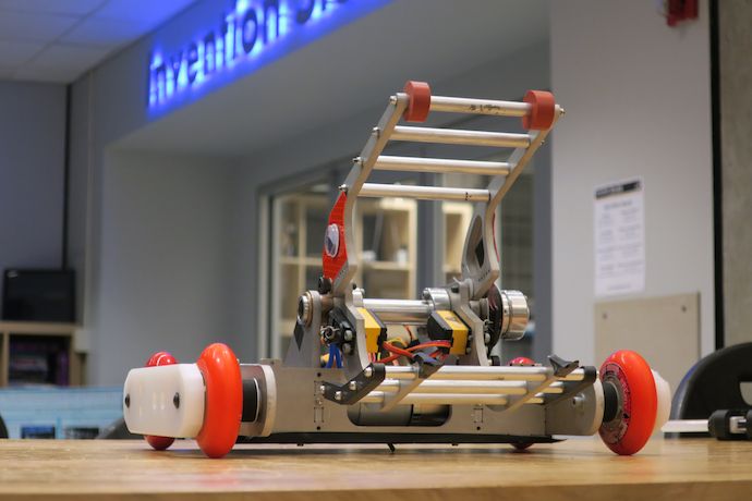
Liftlord
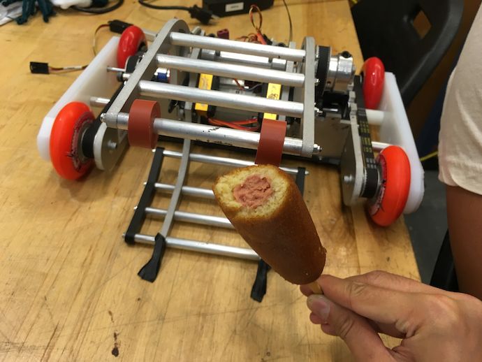
Liftlord is a sumo grappler robot: specifically a (brushless hipster)2 metric 12 O’Clockoff featuring belt drive skate wheels, real hot dog* grippers, servo-actuated clamper, and too many screws.
It wasn’t the idea, but what it became as I rolled with the punches.
Also, it’s not a beetleweight (3 lb)!
Held on Sunday-before-Labor-Day, the micro battles (1 and 3 lb classes) event at Robot Battles at DragonCon grew over the years in competitors while shrinking in schedule, turning into a single-elimination, no rumbles affair. That means half of the entered bots get exactly one fight: less than ideal odds for me considering I had just one win over the course of like ten events. So, it’s time to go big(-ger). Big enough to put me into the 12 and 30 lb fights on Labor Day!
The concept started, as usual, with sourcing motors too big to be useful in a 3 lb. Normally I’d shove them into a Big Data anyways and call it a day†, except this turned out to be a physical impossibility and w-wait… why am I still thinking beetles?
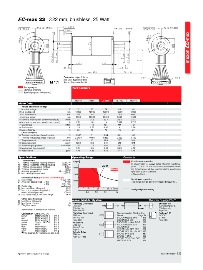
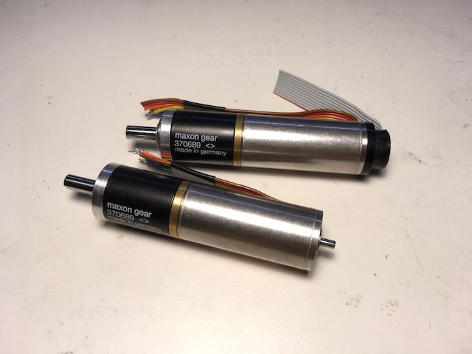
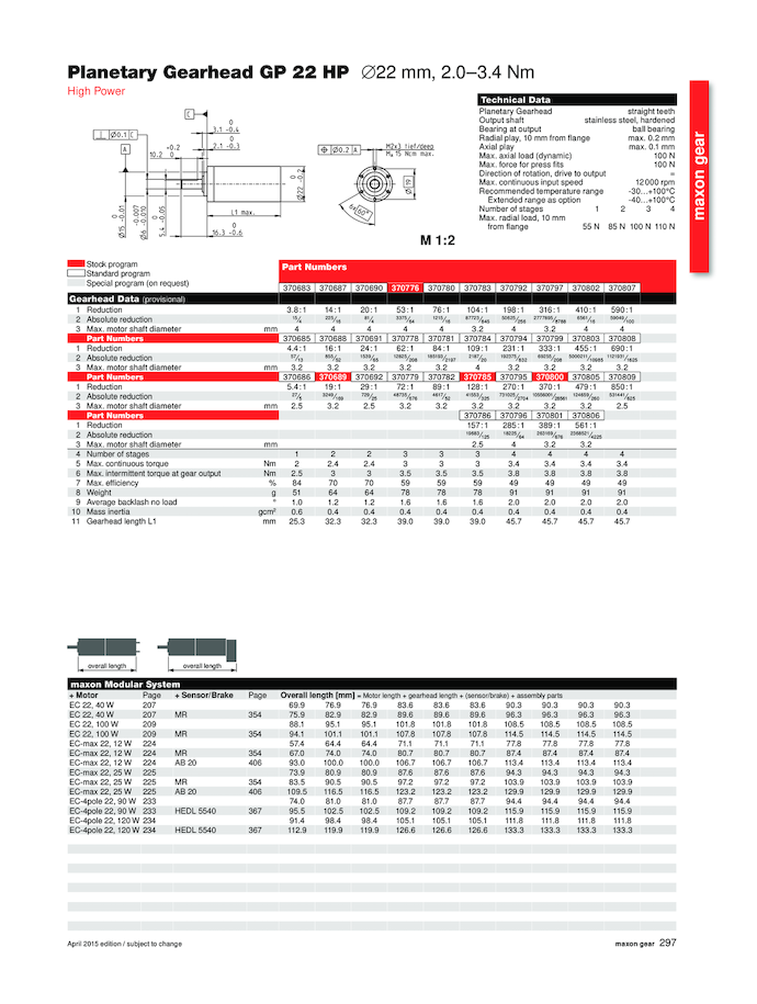
These Maxon gearmotors each comprise a 25 W EC-Max 22 sensored brushless motor coupled to a 19:1 GP 22 HP (“high power”) planetary gearhead. I scored four plus a spare motor (no gearhead) at an average of $45 each.
Now, “too big for beetle” doesn’t automatically mean I can go up to the next weight class. The gap between 3 lb and 12 lb—a factor of 4—is the biggest change in scale between any two adjacent weight classes in US combat robots‡. Compared to the pair of 550-ish drill motors commonly used by many successful 12 lb DragonCon robots, my 22 mm diameter Maxons look positively puny. I mean look at them compared to the Standard RageBridge 2.
Why, then, did I think this setup could work?
- The windings on the motors, rated for 24 V, are relatively “cool.” Even as two-pole inrunners, they clock in at a low, low mechanical Kv of 549 RPM⁄V, a figure you might expect from a 22-pole 50 mm hobby outrunner. As a result, I can expect them to produce a fair amount of torque without running outrageous current through them.
- The motors have Hall-effect sensors that allow their controllers to determine to read—at any speed and within ±15°—the rotor angle and thus the appropriate stator current to produce torque. This helps close the gap between brushless and brushed traction systems at low speed.
- You don’t have to even peek at the datasheets on the planetary gearheads to tell they’re srs business. The 6 mm diameter shaft supported by sealed 696 bearings looks comically oversized relative to the gearhead body.
Running the numbers, I can tell that with a 6-series lithium-polymer pack, this setup can push out similar peak mechanical power to drill motors, but in a smaller, lighter package§. Unfortunately, a smaller, lighter package has less cooling capacity and thermal mass, thanks to lower surface area and actual mass. So average power dissipated during a three minute fight was gonna be a problem.
By the way, the absurd aspect ratio of industrial gearmotors make it look like I’m only mounting them by their face. In actuality, 41% of the overall length of each gearmotor (the entire planetary gearhead, adapter plate, and change) is supported by frame material.
How do you resolve design uncertainty and in the process dip your toes into the 12 lb pool? Build a brick bot with four of these motors for traction to see how things would work out.
except lol jk no I didn’t. Too much pride. Due to the Wang-wedge arbitrary negative double standard (“other people can build wedges but I can’t”), I just couldn’t bring myself to do it and had to put in some kind of active weapon?
Given that exactly one event in the country runs 12 lb sumo fights and it’s dominated by the lifter/flipper–clamper/grappler spectrum, I figured I’d build this new bot as a clone of the most iconic of that event, the 30 lb Überclocker. I even named the CAD model as such:

But ego struck again. I made it a design goal to NOT be like Clocker aside from the overall concept of a four wheel drive grappling bot. This meant no looking at reference photos. It meant intentionally stuffing in different components from what I can recall Charles using. It also meant replacing entire subsystems with silly junk: servos instead of leadscrew to actuate the clamper, no spring legs instead of yes spring legs, belt drive lifter instead of gear drive lifter. After all, it’s not truly Clocker without its lift gear, right?
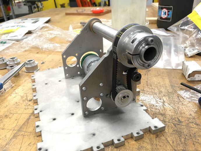
Turns out “not looking” and “don’t rip off” are mutually exclusive criteria. Yes, I avoided the gear drive, but still ended up with a hollow aluminum lifter live shaft running in sleeve bearings with clamp shaft collars for shaft-to-arm torque transfer, because I literally forgot that’s what’s on Überclocker but had enough subconscious fanboy memory to design it like that anyways.
Finally, everything had to be metric. At this point, this has almost nothing to do with round numbers and standardization than to do with my gradual switch to building almost everything with a hefty helping of “Chinesium,” the bot community’s term for materiel sourced (nearly) directly from East Asian suppliers through the likes of eBay, HobbyKing, AliExpress, and Banggood. At first I thought the term implied low quality (for some folks, they’re synonymous) but more accurately it describes the uncertainty of these items’ origin and durability than a clear statement against them. Regardless, Chinesium’s all metric, since little of it is necessarily intended for direct American consumption.
Metric means hardware with metric screw threads, belt pitch, bearing bores, everything but wire gauge and raw stock (don’t give me ideas). It also means components that fit metric stuff: thus 80 mm inline skate wheels made to mount 608 bearings and 775 motor lift motor with a 42 mm gearbox (10 mm output shaft with 4 mm keyway ;). Side note: RageBridge 2’s heatsink mounting holes will clear M3 screws just fine.
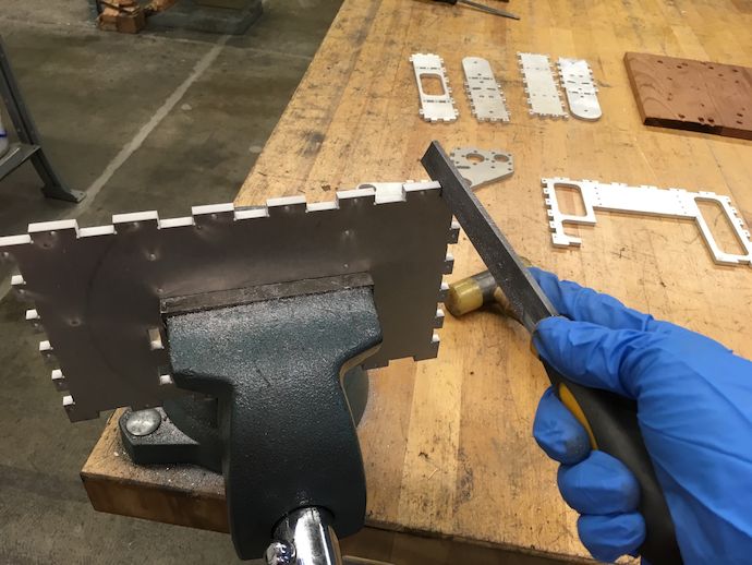
After moving to California and thus away from the Invention Studio, I’ve been in enough of a waterjet drought to have forgotten how to properly design for it. I put in 0.05 mm clearance between tabs and slots in my part, which wasn’t enough for BigBlueSaw’s OMAX quality 3 cut for ¼ inch 6061. Fortunately, I consider manual filing an exciting sub-hobby of combat robotics (and of life, even), so this is A-alright.
As a aside, BigBlueSaw is ludicrous in the best way. The web quote interface literally dumps into a full DXF ingest/process pipeline (written by Simon IIRC) that computes cutting length, number of pierces, image previews, and I assume some approximate part nesting to get you an exact price nearly instantaneously. If that’s just my experience with the frontend, the automation going on from site to machining must be something delightful.
Oh and Julie runs the customer service so if you order parts through BBS, it’s like ordering from team Chaos Corps. ^_^
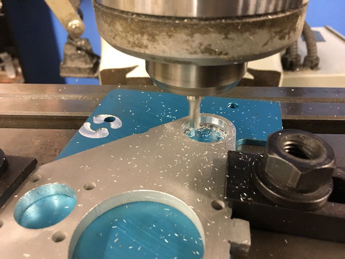
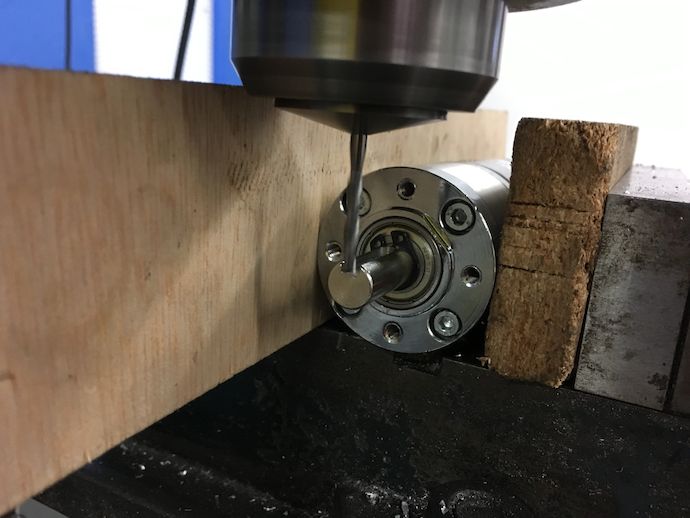
The bronze sleeve bearings for the lift shaft needed an exact circular press fit, so those were waterjat to exact dimension and finished on the Google Workshops CNC mill, although not before I ruined two bearings by pressing them into the rough waterjet bore anyways…
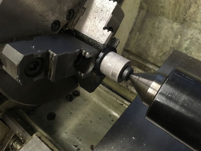
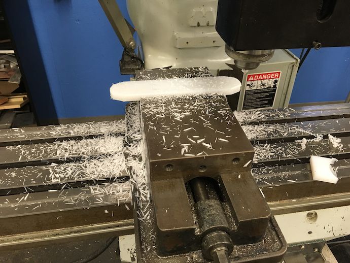
Similar idea here: these spacers (hubs?) go into the 22 mm bore normally occupied by a 608 “skate” bearing, so I’m finishing their outside diameters on the lathe to clean up waterjet taper and non-circularity (waterjets are X-Y machines, after all). The live center was not a good idea. I should have used purely axial force to jam the hubs against the jaws.
Kind of silly but the 4 mm keyway was undersized on this gearhead output shaft, so I expanded it real quick. I should have clamped the shaft, not the motor.
We don’t talk about this.
Or this.
Needs more chmafer.
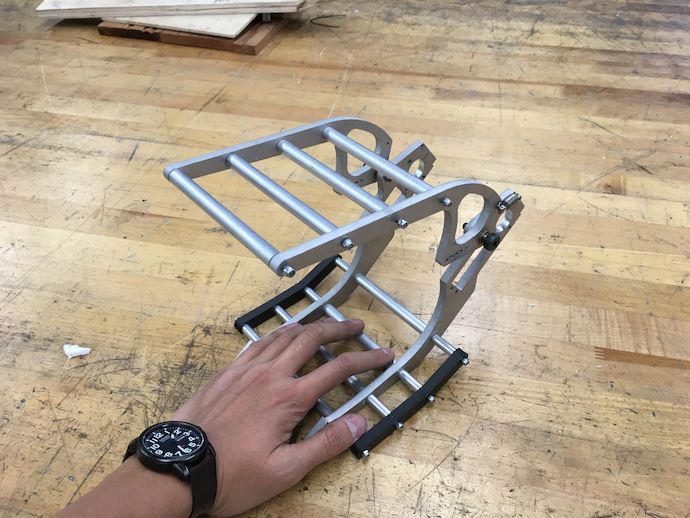
All the black plastic you see is Onyx carbon composite parts that Jamo 3D printed for me on a Markforged Mark Two. These parts are unbelievably stiff and light. The quality of the printing is outrageous; most of the circular bores were designed to exact dimension and ended up perfect press fit. I had originally intended for all the plastic to be milled from UHMW but this opportunity came up and saved me a lot of machine time.
lolservos §
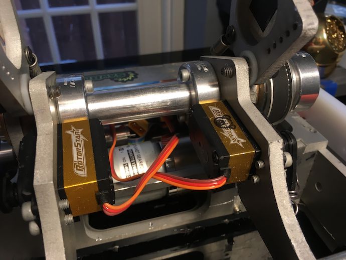
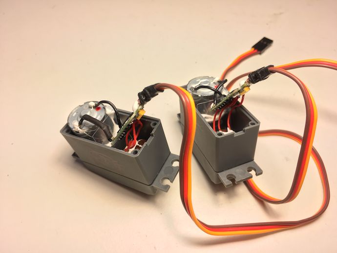
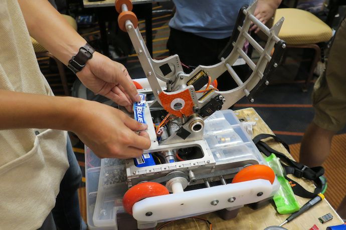
One thing I think is reasonably unique to Liftlord is the servo clamper mechanism. Normally hobby servos are too wimpy to use for securing another 12 lb bot. But I figured if I add a slightly compliant link—in this case, ultra-high molecular weight polyethylene (UHMW-PE) stranded fishing line—and remove the clamper from self-righting forces by using a spring to open the jaws, a pair of “standard” hobby servos might survive combat load. The original idea involved adding even more compliance to the fishing line link with a short high-rate spring on the servo horn, which you can see in the photo (not attached). However, I couldn’t run them as far past their spec as I wanted to. They stretched little before plastically deforming.
I forgot that all this would take up five output channels—two for traction drive, one for lifter, and two for the servos—on my FrSky X4R radio receiver (RX), which had only four: one more than I had ever previously used, except for Gyro King which had a laptop link and PS3 controller.
Why couldn’t I run both servos from the same signal with a splitter? Well, the servos are facing in opposite directions. Running off of the same signal, they’d each spin in the same direction that’s actually opposite directions. I need one servo to run on a channel that’s reversed in transmitter software.
Or do I? What if I were to reverse one of the servos? In hardware?
After all, these servos are just a negative feedback amplifier around an analog potentiometer (“pot”) and a brushed (DC) motor. The potentiometer linearly maps rotary position to analog voltage. If I were to reverse that mapping, say by swapping the pot’s outside terminals, then I’d reverse that mapping, so that the analog voltage now maps to a rotary position mirrored across the pot’s mechanical range.
Finally, I’d have to negate the gain of the controller too, say by swapping the leads of the motor to reverse its polarity, so that the feedback to angular position change remains negative.
Now I have a reversed servo¶!
I tested this on some cheap servos, taking care to mark the servo I reversed. To my surprise, this hack just worked.
Less to my surprise, servo reversing turned out to be a fairly common hack, with docs all over the internet. It’s almost like some people prefer to change things in hardware rather than in software or something.
But of course, the high-power servos I intended to use were outrageously difficult to reverse like this. Its motor, control board, and pot were all one beefy unit hard soldered together. I can’t even bring myself to describe the horrible next level hacking I improvised to make them work.
Epic ship day extrafirmware §
The day before I left for DragonCon, Liftlord’s state was roughly “the parts fit and are holes are tapped.” This left open the problem of how the hell does this move, which, as I expounded on above, was the most urgent and important problem in the whole design. Goes to show how great I am with priorities.
The original least common denominator for traction electronics was to use cheap Chinese controllers (CCCs) flashed with SimonK. This was easy and derpy (because it didn’t take advantage of the Maxons’ sensors): the absolute worst case backup plan, which is to say it was plan A on account of all other plans being not even conceived.
Unfortunately, SimonK’s default startup routine didn’t “take” on my motors. I didn’t want to figure out why or do the tuning because I wasn’t confident I could make it work in 12 hours. So time for plan B, which as I mentioned, didn’t exist or anything.
UHHHHHHH.
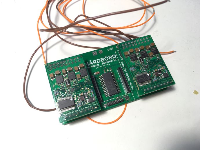
I started going through random boxes on my shelf because I figured, WELL DANG I should be able to drive some motors. What do I find but the control/power distribution board from HÄRDBÖRD, complete with PIC24, XBee module, and most importantly Maxon DEC 50/5 motor control modules.
This was maybe the second or third printed circuit board (PCB) I had ever designed, from way back in the heady days of 2010, and part of the first thing I ever worked on with Jamo. It even has a BatchPCB ID mark on it, from the times when hobbyists were willing to wait two months for PCBs and we were happy to do it because they had white silkscreen on green soldermask just like the pros and only for like fifty bucks my god this is so amazing we’re living in real time like all effecting a desktop manufacturing REVOLUTIONNNNNN.
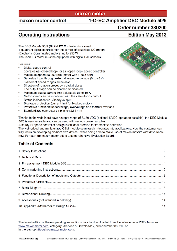
Once I came down from the Bre-stolgia, I dug up the docs for the modules and found that they have a 0–5 V input for speed control, an enable pin, and a direction pin. This meant that I needed a microcontroller to convert the digital pulse-width modulated (PWM) signal of my receiver (RX) into what the DEC 50/5s understand. The PIC24 code on the board actually did something similar: convert Wii Nunchuk data received over XBee to Maxon DEC analog. Unfortunately I couldn’t find a 16-bit PIC programmer anywhere so I couldn’t just hack up that code; I’d have to find a small, general purpose microcontroller to use in the PIC’s place.
You might expect me to be trippin’ boards. But I don’t normally need small, general purpose microcontrollers because my projects tend to be the opposite of general purpose. So I don’t have any Arduinos Micro chilling about. Or mbeds LPC1768. Hell, I didn’t even have an STM32FxENDEAVOUR.
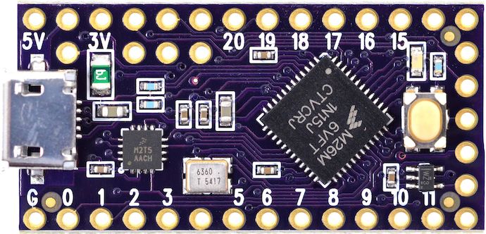
What I did find was a Teensy LC purple edition in a fiber grocery tote that I scored in some swag bag at a computers conference (both the board and the bag). This… this is my San Francisco life.
This is the “low-cost” (LC) version of a Teensy, using a ARM Cortex-M0+ core Freescale microcontroller that has non-5 V tolerant input pins. This means that the Teensy LC can’t directly take the 5 V “READY” signal from the DEC modules. More critically, it also means I can’t slap a pull-up resistor to 5 V onto an open-drain PWM pin and expect 5 V PWM output, with which I’d use to synthesize 0–5 V analog. I need a level shifter for each input and a buffer (or level shifter, which is like a bidirectional buffer) for each output.
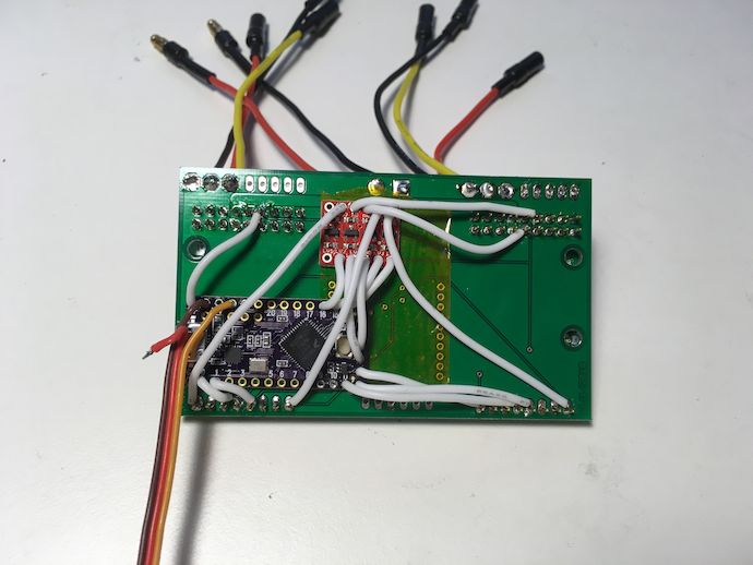
I ended up wiring things up “dead bug” style on the back side of a blank HÄRDBÖRD PCB. The red board is a SparkFun Logic Level Converter – Bi-Directional with four level shifters. The Teensy LC itself also has a 5 V-buffered PWM output, which I used. The DEC modules’ digital inputs have 2.4 V thresholds, so they didn’t need buffering from the Teensy LC. But wait, why is the the 5 V digital PWM output connected straight to the DEC module’s speed value input? Don’t you need to filter it to analog? Isn’t the 10 kΩ output of the level shifter too high compared to the 107 kΩ DEC input impedance? The answer is the same as always: STFU about my hardware bug and fix it in your firmware.
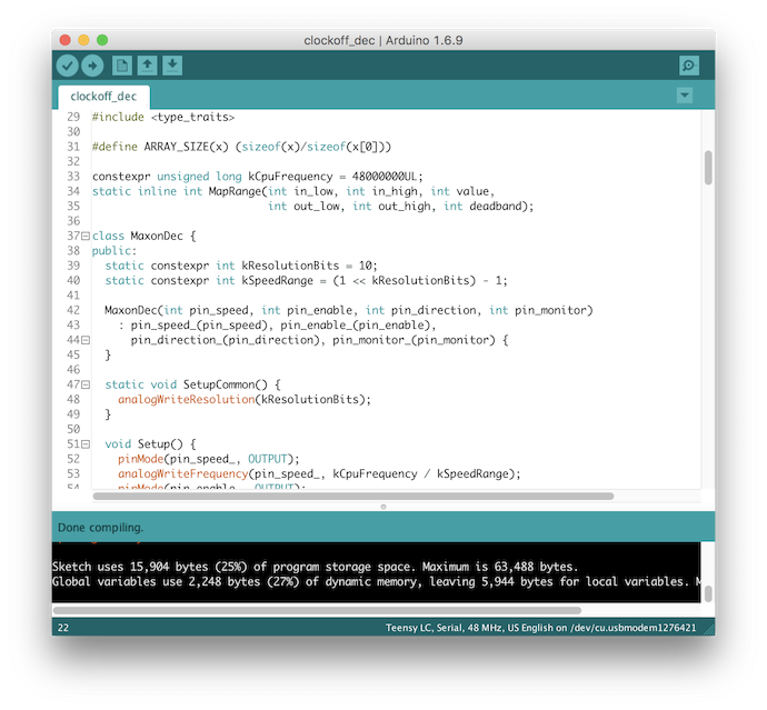
Teensy uses the Arduino IDE and libraries. They mostly don’t get in the way of writing normal C++, except for egregious novice mistakes designed into the Arduino library like min/max macros. The libraries are extended with additional calls by Teensy. The Teensy-specific extensions saved my bacon this time, because they include analogWriteFrequency and less critically analogWriteResolution, which allowed me to run PWM output at CPU frequency / (1024-step resolution), or roughly 47 kHz.
This was apparently fast enough to be cut out by whatever low-pass filter was on the DECs’ speed inputs.
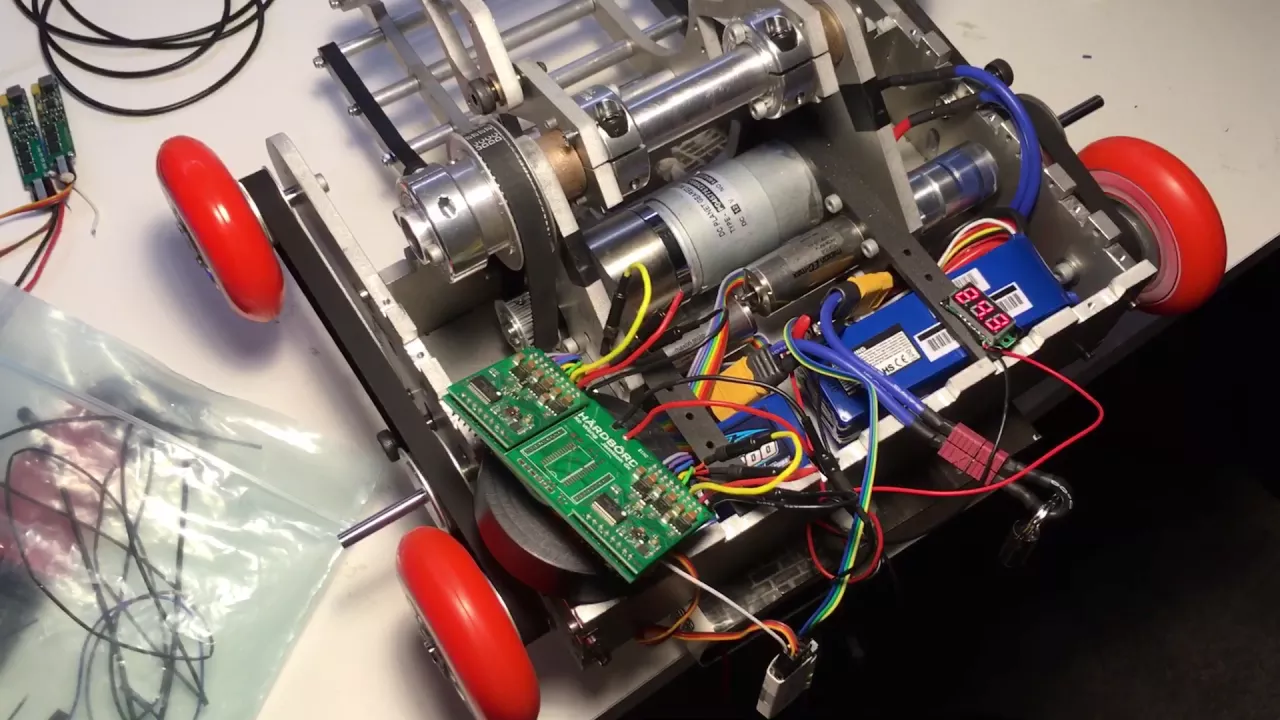
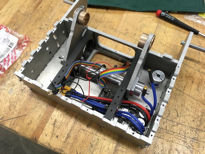
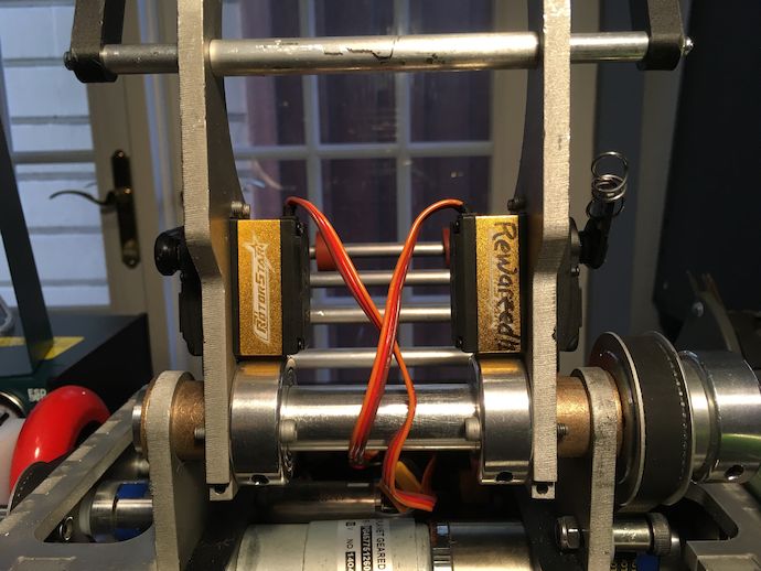
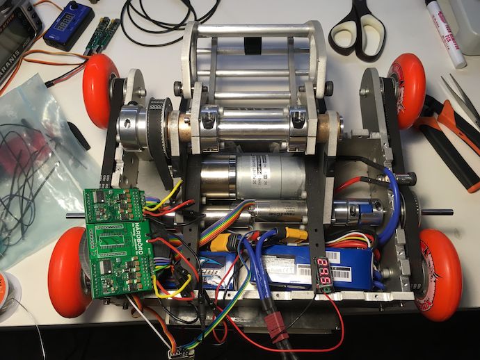
Now you can see that all of my belt tensioners are M5 shoulder screws with sleeve bearings, bolted into frame slots with nylon lock nuts. Also, jaw/spider shaft couplers because why not.
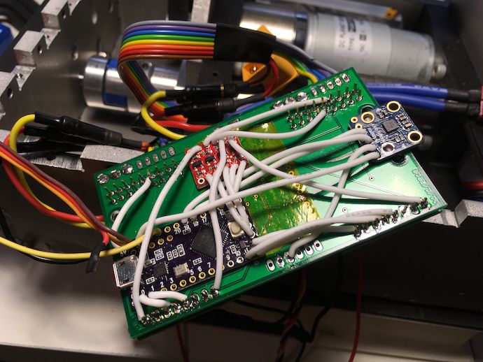
Once I realized it all worked, I threw on an IMU (why not?) and mummified it all in electrical tape. Oh, remind me to never again use high strand count silicone-insulated wire for board-to-board connections because you have to twist and tin stripped ends before soldering them to pads. Huge PITA.
Weapon testing §
Around this time I also discovered that my attempts to engineer out the uncertainty around the 27:1 775 Chinesium gearmotor might have landed this bot well into overkill territory. It was no longer accurate to call it a lifter, since it was more than happy to toss my 3 lb bots into the roof at 50% transmitter rate gain and lowest RageBridge current limit. It blurred the lines between lifter and flipper.
DragonCon §
DragonCon 2016, held in downtown Atlanta, GA on Labor Day weekend, was whatever DragonCon is. It’s hard enough to describe DragonCon relative to what I think other cons are like, but it’s impossible to explain in absolute terms. Instead I’ll just point out that it has the second-oldest robot combat competition in the world and fascinating cosplay.

Actually, I’ve been given plenty of chances to plug DragonCon cosplay and never did. I shouldn’t pass up this one.
DragonCon’s lack of focus on any particular genre—though it’s heavy on fantasy and sci-fi—gives it a multifaceted identity that bleeds into its cosplayers.

This and the participants’ devotion to their product results in very eye-catching costumes that don’t necessarily reproduce characters from any particular intellectual property (IP).

In fact, some of my favorite costumes are the ones that juxtapose unrelated IPs, generating humor by surprise and sometimes détournement. Iron King Triton is pretty emblematic of DC’s “why not” remix cosplay performance.
My favorite three elements of DragonCon came in one hella splendid mishmash this year: battlebots, cosplay, and my friends. Check it outtt: cynaesthetics: FEMALE HANZO + BATTLEBOTS COSPLAY
They did some outstanding work. I’m in total awe at the hustle they and other folks at Con put into their various projects, all of which I consider performances: parade costumes and vehicles, knowledge exchange panels, even prepping themselves for partying is a planned endeavor. I got some sharp regret for not walking around with a camera; after all, I had less to work on so I feel I was obligated to capture it all. Instead, I have three photos of food. Thanks, everyone else who did document!
Competition §
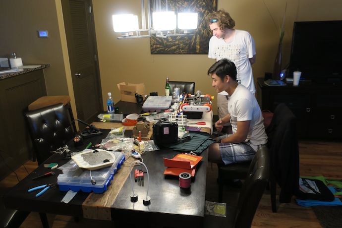
After all that, I became uh, indisposed. So Aaron drove Liftlord for me. He had brought a 3 lb flail bot, which fought in the previous day. He’s better at driving Liftlord than I am without having even tried it previously, while I had at least 20 minutes of driving practice.
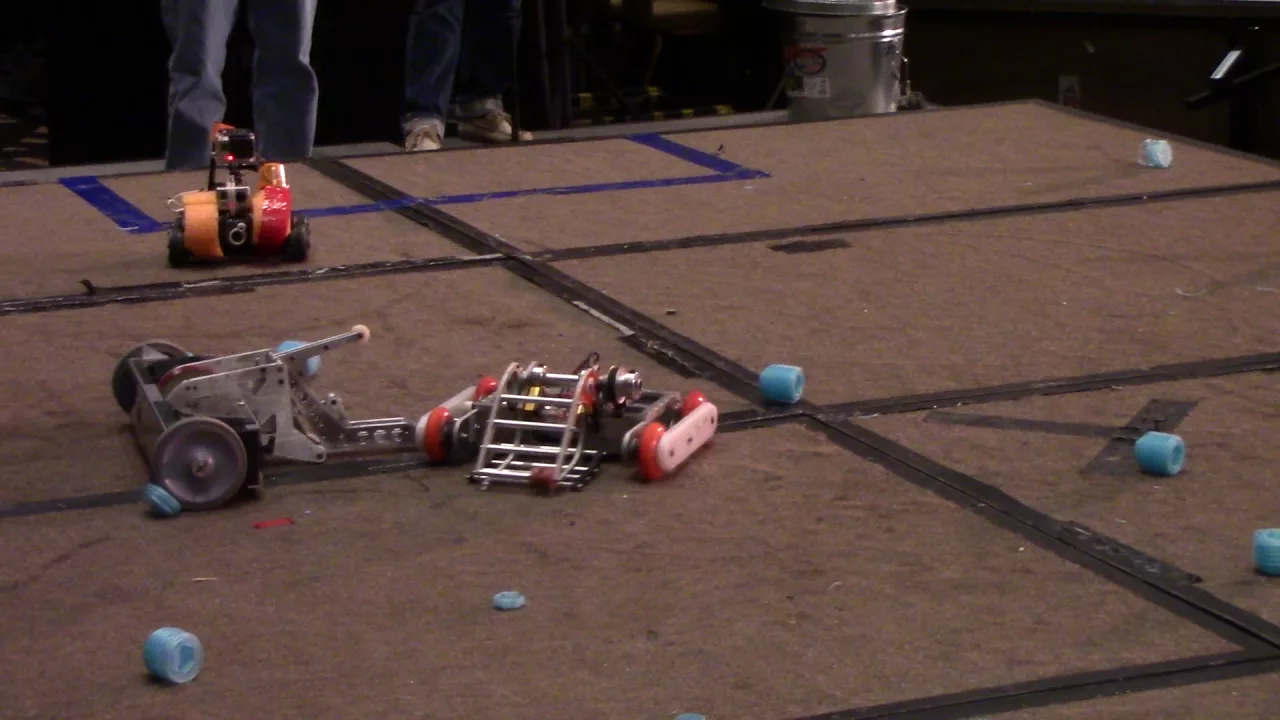
In fact he even beat DragonCon Bronco, Dale’s T-Boner 2.0. I can’t help but admit that the win, as well as the first win against Jason “Evil” Brown, were aided in part by malfunction in their bots.
I think Liftlord eventually exited the bracket as a quarterfinalist? I’m kind of hazy on that one. Oh did I mention that the tournament was single elimination, just like the insect (1 and 3 lb) classes? There goes 50% of my motivation for building a stage bot.
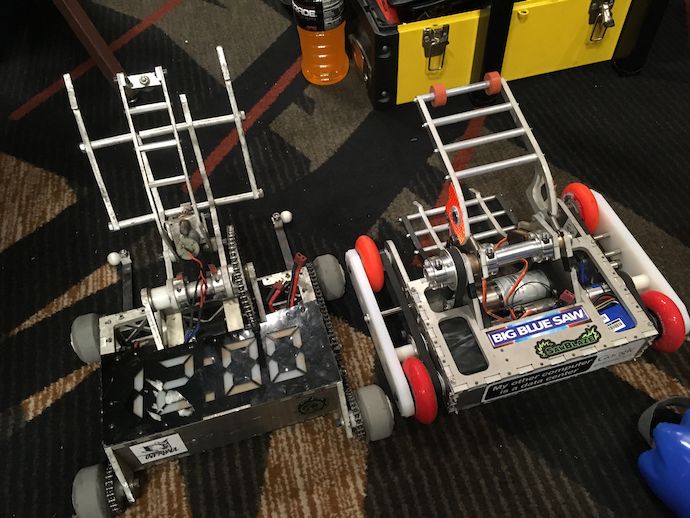
I was giddy seeing this side-by-side because I honestly didn’t expect Liftlord to be so similar to Charles’s 12 lb version of Überclocker, 12 O’Clocker, given my requirements on “not looking at references.” It’s not as adorable as 12 O’Clocker though.
Meanwhile in the 30 lb class, Andrew’s Pusheen, a wooden bot (also brushless hipster, maybe even more so), won against Near Chaos’s chainsaw bot. It’s even better than the time Wedgee took out team Invention Studio’s assbot. #dragoncon

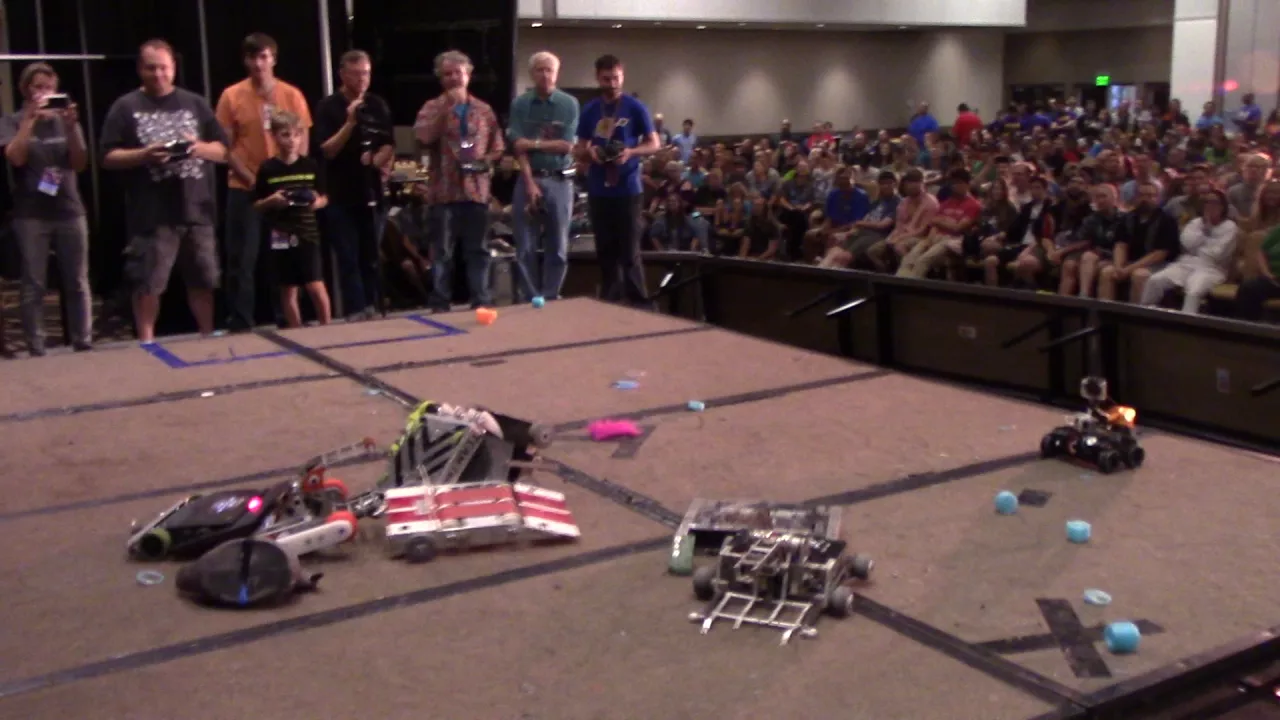
Finally I got up to the stage for rumbles. As I understand, I won the second one but as I continued to be uh, indisposed… I don’t really remember it. I’m feeling too embarrassed to watch the video since I was probably driving like derp.
Driving this bot really made me realize what a nonsensical amount of coordination is required to pull off a Charles-style grappling performance. And Liftlord’s clamper has position control while Überclocker has first- or second-derivative control. I had decided while practicing before the tournament that I wasn’t even going to bother with the clamping. I just wasn’t able to do the whole maneuver-scoop-clamp-lift sequence with authority. It also helped me appreciate what a huge hindrance the stage risers’ joints were to bot mobility. If you don’t raise the lifter wedgelets and keep them raised, they will jam beneath the cheese-grade steel frame. I’m impressed with the practice that the veteran bot builders must have put in to put on the show that they do.
This is actually my first win at DragonCon in I think six odd years of trying to compete in it. I felt kind of validated that I could suppress my urge to build nutty curios and put in the attention to detail—Loctite every screw, wrap all electronics—to enter something competitive. It pointed out driving as something to work on: my crappy tournament record and frequent malfunctions means I’ve had relatively little arena time in the years I’ve been doing this hobby. Maybe it’s time for a strategy rework? ∎
Shouts out to Jamo for the Markforgery, Aaron for the hacks/driving/photos, Wes for googly eyes/tape work, Big Blue Saw for their help, and everyone else at DragonCon 2016 who made it an incredible experience.
Specifications §
- Frame waterjet cut ¼ in 6061 aluminum, 3D printed Markforged Onyx chopped carbon fiber nylon bulkheads, computer numerical control (CNC) milled ½ in ultra-high molecular weight polyethylene (UHMW-PE) armor
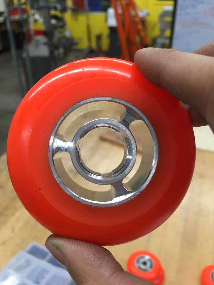
- Wheels 4× 80 mm Shore A 74 durometer indoor inline skate wheels each running on 2× HK0810 needle roller bearings inside 22 mm hubs through-clamped to pulleys
- Lifter motor AndyMark PG27 Planetary Gearbox with RS775 Motor♠
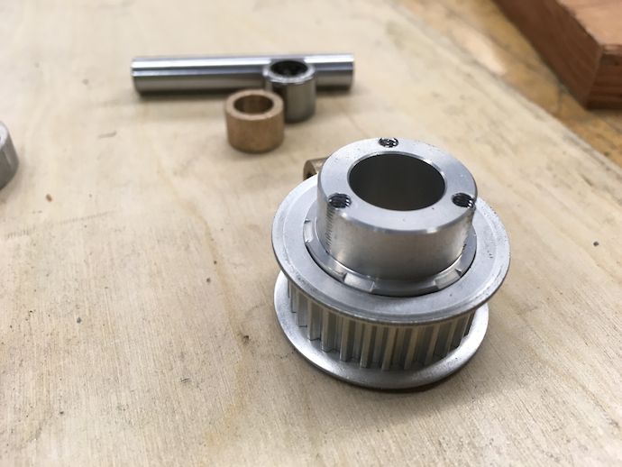
- Lifter final drive 25-tooth 3 mm diametral pitch timing pulley driving 50-tooth pulley through fiberglass-reinforced rubber timing belt; driven pulley is screwed to clamp shaft collars driving 20 mm outside diameter (OD) 2024 aluminum hollow shaft
- Lifter controller Equals Zero Designs RageBridge 2 in single-input mode, at minimum current limit
- Traction motors 2× 24 V, 25 W Maxon EC-Max 22 sensored brushless motor each coupled to a 19:1 Maxon GP 22 HP planetary gearhead
- Traction final drive 2× 36-tooth 3 mm diametral pitch timing pulleys driving 4× 30-tooth pulleys through fiberglass-reinforced rubber timing belts
- Traction controller 2× Maxon DEC Module 50/5, digital 1-Q-EC Amplifier with half-resistance current sense shunts, soldered to custom power distribution board, controlled by Teensy LC
- Clamper motors 2× RotorStar RS-550MGC-HV Helicopter Cyclic BB/DS/MG Servo (ball bearing, digital, standard, metal gear)
- Traction and lifter batteries 2× ZIPPY Flightmax 2200mAh 3S lithium polymer, in series for 22.2 V
- Clamper battery Turnigy 800mAh 2S lithium polymer, 7.4 V