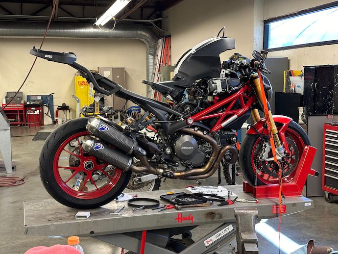
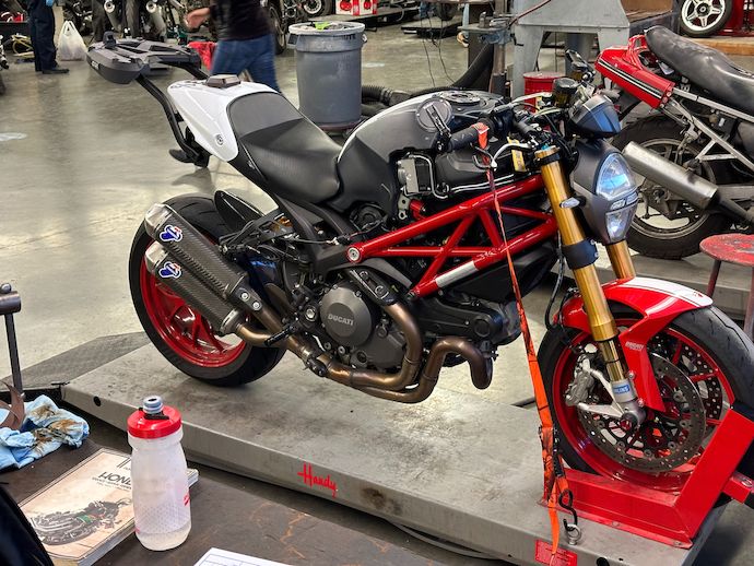
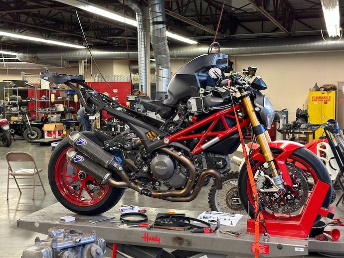
One of my obsessions of the past year has me pouring my anguish over the (twice!) theft of my fourth-ever motorcycle, a 2014 Ducati Monster 796 ABS, into its replacement, a 2012 Monster 1100 EVO, in the form of a fat tools & parts budget and sweaty wrenchwork.
But I’m still gonna cheap out on maintenance by doing it myself, so here’s how I changed the timing belts.
I bought this bike used in 2021 and the first steps were to get it into the shape that most resembled my lost 796. This was cosmetic at first—removing a few aftermarket bits I didn’t approve of* and repairing some misguided “previous owner maintenance.”
Before long, I realized that minor provocations like discovering a “previous owner” hardware store machine screw in lieu of an Italian-made TCEIF awoke an anger in me that derived from the devastation of stepping out the door to find an empty space where my motorcycle should be. I knew what I needed to do to make myself whole from the horse theft: get this bike into shape, by the book, clawing back the opportunity taken from me to wrench on my 796.
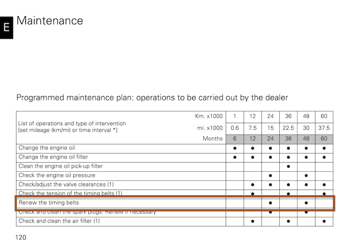
In particular, because this is a relatively recent iteration of Ducati’s traditional air-cooled Ducati 90º V-twin 2-valve† engine, the “by the book” method has a few refinements to get the tension and timing right.
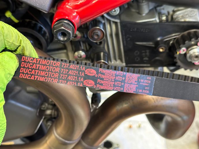
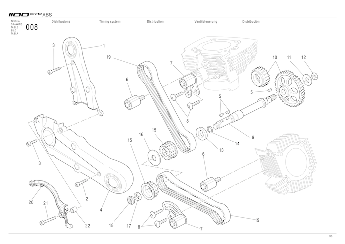
Timing belts Of course, given the desire for purity in this project, I’m opting for Ducati OEM belts, part 73740211A. I got a pair from a Ducati Coventry eBay listing in September for £103.16, working out to $167.58 after international shipping and local tax. A quick search shows that there’s lower cost US stock right now, so it hardly seems worthwhile to use aftermarket belts at around $100/pair.
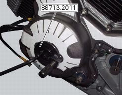
Crankshaft turning tool with TDC lock This Ducati-specific tool (part 887132011) turns the crankshaft and also screws into the case at top dead center (TDC) timing to hold the crankshaft there. I used a Laser 6361 because almost all of the aftermarket tools looked better made than the Ducati one.There’s also a similar crankshaft turning tool, advertised as a replacement for Ducati part 887130123. These aftermarket tools are a bit chunkier because they have a turning handle rather than an hex boss for turning the crankshaft key and—more importantly for regular maintenance jobs—don’t have a locking screw for TDC‡.
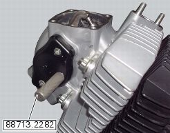
Camshaft locking pins Another Ducati-specific tool (part 887132282), each of these pins thread into the engine case and engage an indentation on an camshaft at some valve timing datum that lines up with crankshaft TDC. This secures the the camshaft and, more importantly and as I’ll get into, actually sets the timing on these later model motors. I bought the Laser 6367 set, which again looked better than the Ducati set, but they’re just pins with M8 threads so I only had cost in mind.
Torx T30 driver My engine uses timing pulleys assembled from two (functional) pieces: a hub keyed to the camshaft that clamps a floating toothed pulley using arced slots.The clamping force is provided by Torx head screws§, so an appropriate bit is required to drive these.
Spark plug wrench Removes the spark plugs in order to allow the pistons to move freely—I was not gonna be able to crank a 1078 cm3, 11.3:1 compression engine by hand otherwise.
Electronic frequency measurement tool The Ducati timing belt tension is actually specified and measured indirectly as its plucked frequency. Recall that the natural frequency of a string under tension is proportional to the square root of its tension force, so this is pretty reasonable if other properties are held constant—which is only true if I measure OEM belts, and recently-installed ones at that because of their alleged 24-month lifespan. Is this an overly-zealous engineering-to-maintenance transliteration or an Italian nanny-stealership service interval conspiracy? I opted for the Gates app¶ to measure the frequency with my phone.
To prepare, I removed the painted fuel tank covers, which leaves a very naked-looking naked bike, then put the seat back on.
Strapped and chocked
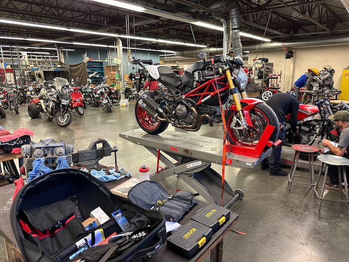
I rode it over to City College, where I’m enrolled in motorcycle tech classes and can pop my bike onto a hydraulic work lift. This is a short enough job that it doesn’t need a lift but why risk my back if I don’t need to? However, this does mean I need to wait for the engine to cool down before I can start wrenching.
Even more importantly, while here I can tap into my instructor Andy Saunder’s vast knowledge of motorcycle maintenance, especially his decades of practical wrenching know-how.
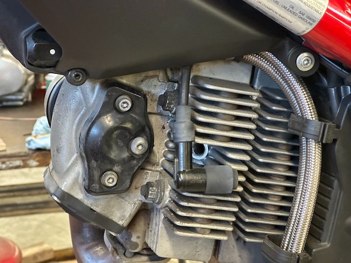
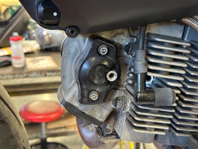
I start on the left-hand side of the bike, where the crankshaft access port, camshaft covers, and spark plugs live. The spark plug boots pop off the spark plug terminal with moderate force.
I still can’t believe spark plug boots are held on like this
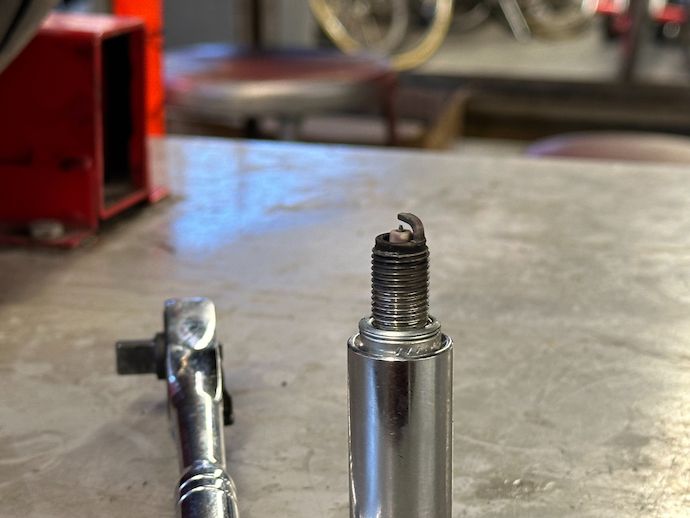
Then I unscrew the spark plugs with a deep 5⁄8″ hex socket.
Horizontal (front) cylinder, hence the grunginess and different orientation
Any time the spark plugs are out is a good time to “read” their residue color.
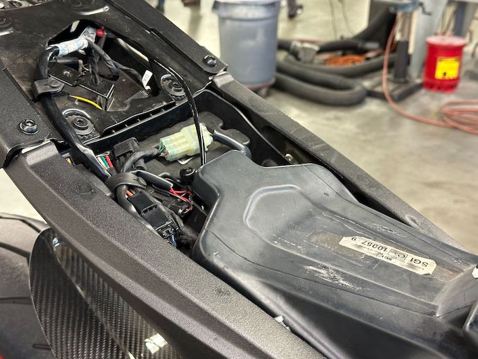
The timing belt covers are on the right-hand side under the trellis frame and some wiring, so they come out by sliding along their length rather than lifting from the engine. So, I slide the vertical (rear) cylinder timing belt cover upwards towards the tank, which I then lift to clear the cover.
I already removed the necessary retaining screws, so the tail of the tank pops out of the subframe with some persuasion.
Ignore the extra wires and gaping void…
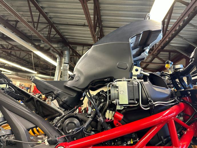
Then I put the tank into a position familiar to shadetree 696/796/1100 mechanics: fuel pump resting♠ on the vertical cylinder and front brackets resting on the airbox. This position obviates unhooking any fuel lines or even putting the tank on a nearby surface.
Besides the fuel tank, my Bazzaz Z-Fi piggyback fuel controller harness is also in the way♥, as is the lengthy crankshaft position sensor connector.
The vertical cylinder cover slides up, as mentioned.
I marked Bazzaz-related wiring with yellow zip-ties, so there’s the Z-AFM subharness right in the wayTarget sighted
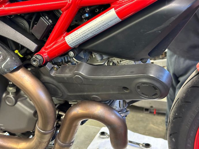
The horizontal cylinder timing belt cover is a bit trickier because it’s larger and has to go around the EVO’s right-hand exhaust header routing.
I really should have loosened the headers for thisAt least the plastic covers flex a bit and have a less critical finish than carbon fiberWhile I’m here, the heat shield comes off for a bit more clearance
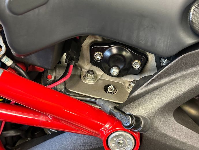
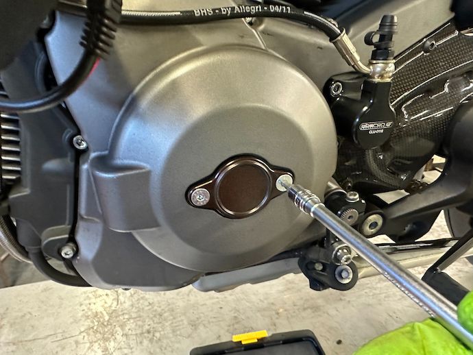
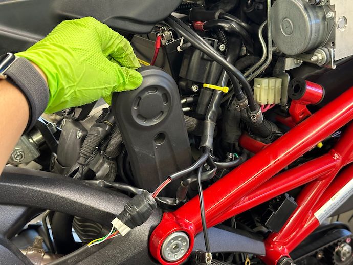
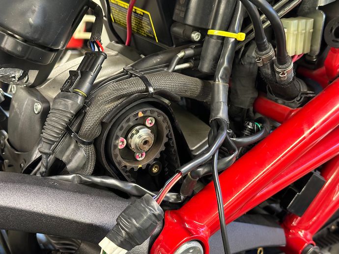
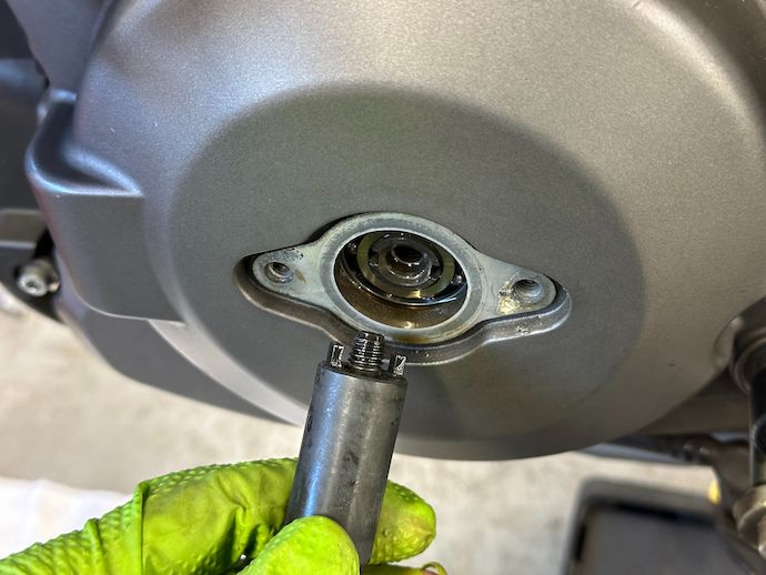
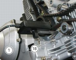
Next I was ready to start the actual work of doing the timing belt change. I mount the crankshaft turning tool by first lining up the dogs on the tool to their seats in the engine on the left hand access port.
The oil level is well below this port, but there still will be some oilThe inner socket head cap screw tightens down into the crankshaft
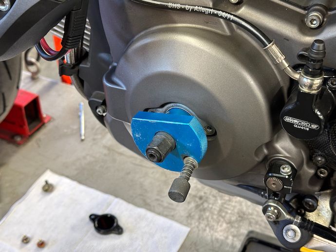
With the Laser 6361, the internal crank-turning spindle spins freely until set screws in the blue locking collar are tightened into specific spots on the spindle. The locking collar also has that spring-loaded locating screw that screws into the holes for the port cover. When the engine is at TDC, the set screws and the locating screw all line up to their holes so that they can be tightened down and lock the crankshaft in place.
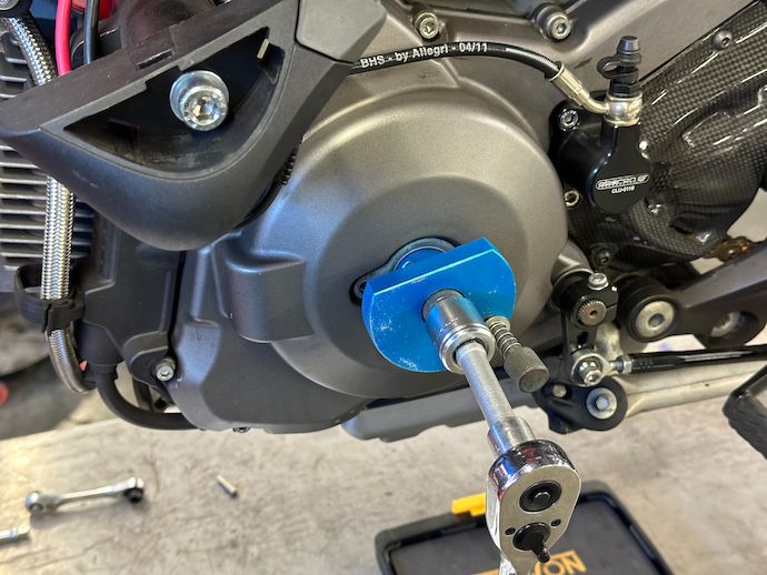
The outer hex allows a ratchet or T-handle to turn the crankshaft
I’m actually leaving the crankshaft unlocked right now, but I do need to find TDC.
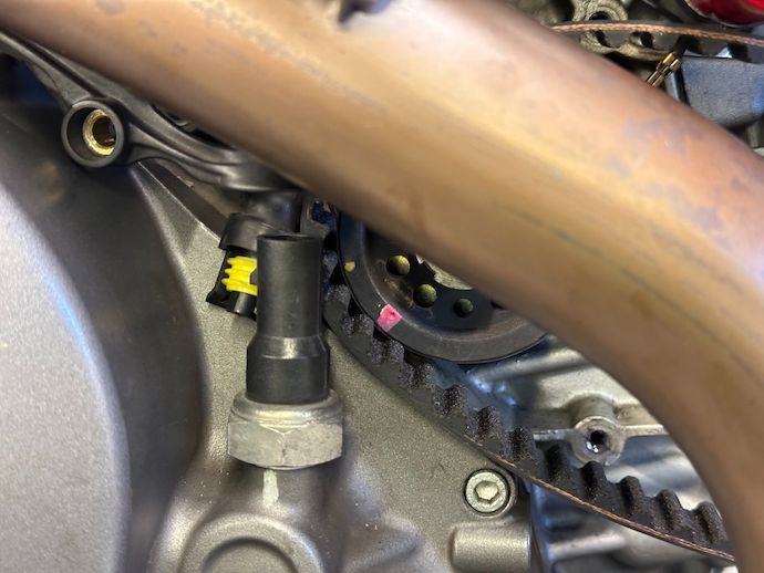
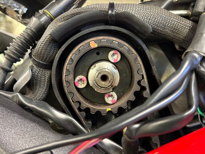
I observe the timing dot mark on the central pulley♦ and turn the crankshaft until it aligns to the line mark on the crankcase, then lock the tool to the cover.
I turn using the tool with the gearbox in neutral but I think it could be easier to have the rear wheel on a stand and the gearbox in sixth gear, then to turn the rear wheel without going between left and right sides of the bike to check the dot-line alignment.
Next, I gently thread in the camshaft locks into the left-hand camshaft port while slightly jiggling the crankshaft. If it goes well, the camshaft locks will sit completely bottomed out, with the pins engaging with indentations on the camshafts.
In my first try doing this alignment, I didn’t use the pulley mark, just the holes on the crankshaft access port, and couldn’t get the camshaft locks to engage. Recall that the crankshaft turns twice as quickly as the camshafts because its job is to convert the linear piston motion to rotary motion, while the camshafts actually govern timing through the four-stroke cycle. So the crankshaft puts each cylinder at TDC twice per rotation of the camshaft. What’s more, the crankshaft locking tool can be locked to either of the 180º-offset cover holes, with a possible 90º set screw offset. This allows locking at four different positions per crankshaft rotation: TDC or BDC of either of the cylinders, which are 90º out-of-phase.
So, I had only a 1⁄2 × 1⁄4 = 1⁄8th chance of lining up the camshaft to the mark on the case—specifically for the horizontal cylinder at TDC just before its power stroke—by simplying picking one of the possible crankshaft locking positions.
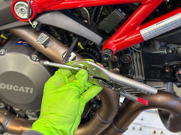
Now’s a good time for me to loosen (but not remove) the timing belt tensioner screws. On my bike, these were well over-torqued past their 26 N·m ± 10 % spec, so they needed some creative unscrewing.
Slightly abusing my Motion Pro 08-0389 T-handle wrench using C.H. Hanson 06100 locking pliers to loosen tensioners
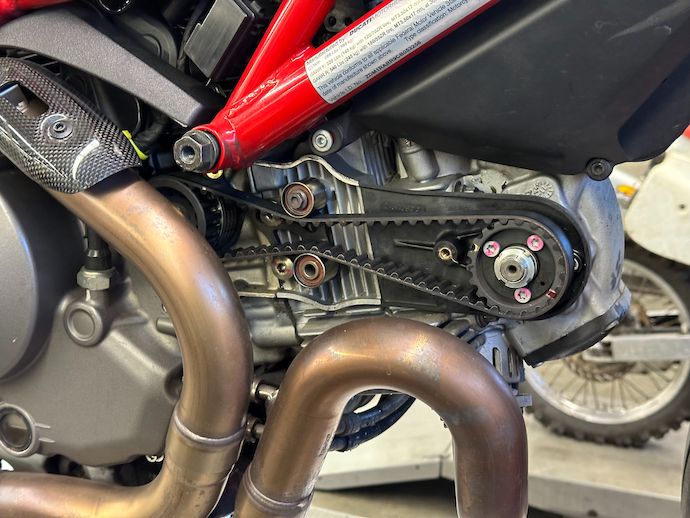
Next, I move the tensioners away from the belts to loosen them. With the extra slack in the timing belts, I work them over their pulleys’ flanges and through the gap against the engine case.
The vertical cylinder’s timing belt is stacked underneath the horizontal cylinder’s
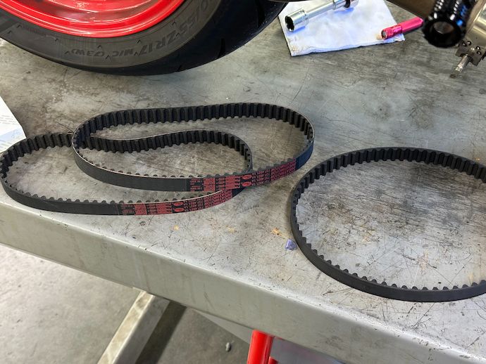
Here, I discover that one of the major differences between the Dayco aftermarket belts I found in here and the OEM belts is that the former is quite a bit thicker and less flexible.
There’s that limpness we paid for
The difficulty in pulling the aftermarket belt through the gap between the pulley flange and crankcase alone made the thinner OEM belts’ extra cost worthwhile.
Hehe, too-thed
I give each of the tensioner rollers a few spins to feel for crunchy or bound-up bearings. This bike has lived in California for its entire 12,000-mile life, so these sealed bearings♣ haven’t seen much weather abuse; the risk I want to account for is misguided maintenance, e.g. overtensioned belts or even solvent intrusion.
After this, I break to panic about whether I’ll ever get my motorcycle back together again. This usually lasts five and a half minutes.
Somehow it feels worse every time despite the bike looking way more complete than after my usual disassembly
Installing the new belts is the reverse of the removal procedure, except for being a bit more careful about the new belts since they’re not being taken out of operation.
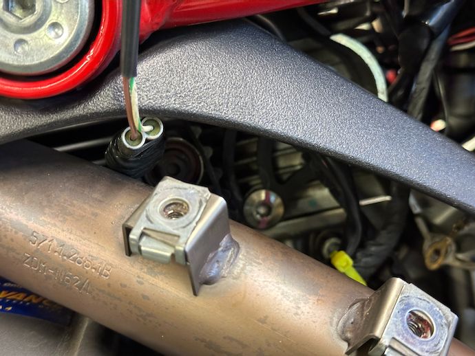
I had to disconnect the crankshaft position sensor for clearance to remove the old belt, but the slimmer OEM belt went in smoothly
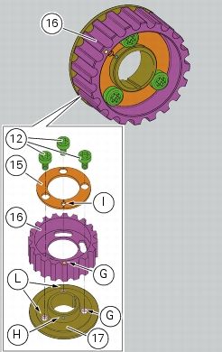
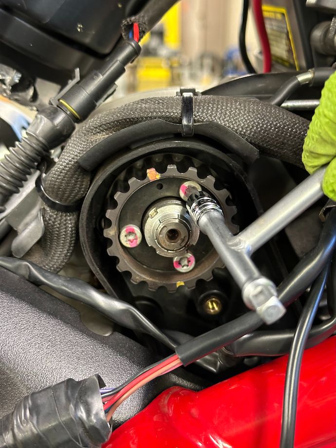
The big change for these recent model 2-valve Ducatis is in the adjustable pulleys. Recall that the timing pulleys have the toothed portion mounted on slots over a hub that’s keyed onto the camshaft.
Because the camshafts are locked in place to their factory timing datums, as is the crankshaft and central driving pulley at their corresponding position, these free floating pulleys aren’t for changing cam timing—rather, the opposite, to prevent the timing from drifting while setting the tension for the belts¤.
I start to float this pulley on its hub and realize it’d be better to do it with the belt mounted so that the float can’t shift the pulley by a full tooth from nominal position
The procedure is to mount the belts, loosen the clamping screws with a Torx bit, adjust and set the tensioners, then tighten the pulley clamping screws. This mechanism decouples the pulley driving responsibility (belt velocity) from the valve timing responsibility (phase between crankshaft and camshafts), which tickles my software engineering brain just the right way. Compared to the traditional way of mounting the belts at the same tooth positions, this has two advantages:
It’s relatively immune to timing changes: the crankshaft and camshafts are locked and can’t be jostled out of position if I sneeze.
With the belt driving a free-floating pulley wheel instead of the desmo valvetrain, there’s less friction on the belt-train as I move each tensioner into place, allowing the force to distribute into the idler run of the belt.
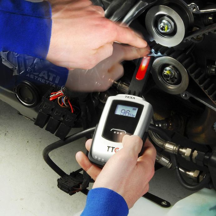
“Traditionally,” belt tension is measured by testing measuring the belt’s deflection under a known orthogonal load. The “dark arts” shadetree procedure calls for passing hex keys past the belt idler rollers, with 5 mm and 6 mm used as go/no-go gauges.
Ducati’s workshop manual instead calls for the € × 10³ DDS dealer shop computer and an out-of-production “kit tensionamento cinghie” to measure the plucked frequency of the belts.
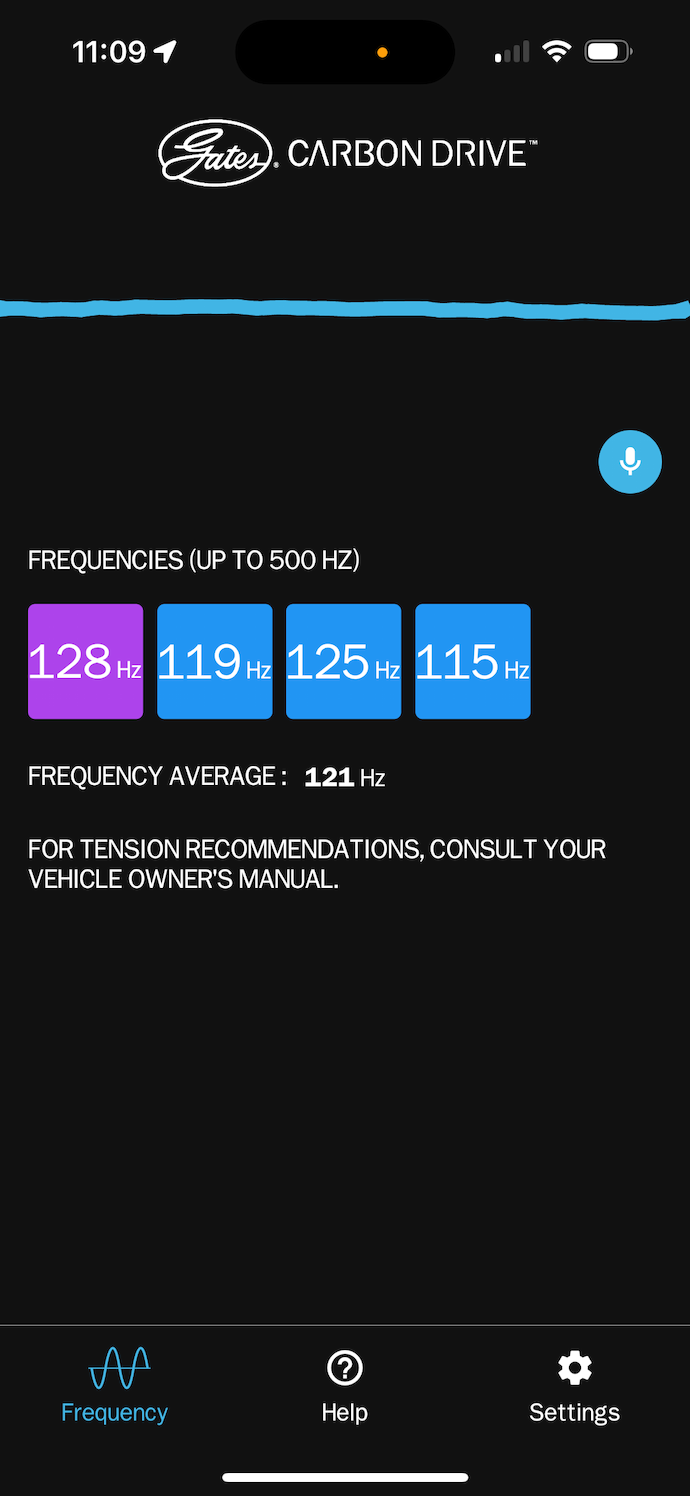
Meanwhile, I figure frequency is frequency and use what is effectively a guitar tuner app to pick up the timing twangs with my phone.
I took this screenshot while playing around; it measured my plucks in anger with even less variance
I’m sure that I don’t have the best acoustic setup: I hold my phone up to the belt, resting its case against the engine cover to dampen out some hand jitter.
After setting the belt tension to its 140 Hz ± 5 Hz, Andy and I do a “belt and suspenders” check with the hex key method and discover that despite having similar acoustic measurements and “felt” tension, the horizontal cylinder belt is allowing way less deflection off of its idlers than the vertical cylinder belt. This observation seems to be corroborated here for its sibling M1100S engine, suggesting that the deflection tensioning method might have been obsoleted.
However, it did raise the question whether the tension spec was correct. Based on “Internet said so” evidence, it seems that the spec was downrated to 110 Hz across a number of Ducati models, including the 1100 EVO. That’s what I’m going with—based on the experience I gained doing this, it’s now a low mental barrier to check the frequency frequently to make sure that the tension doesn’t drop much further.
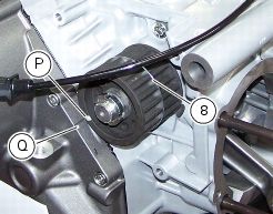
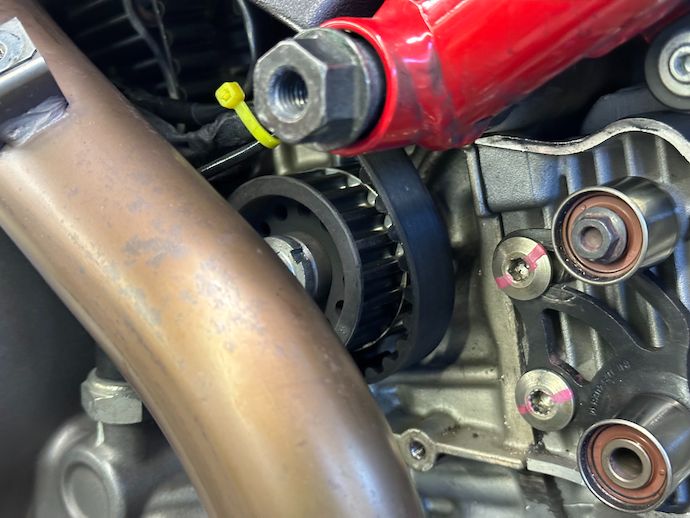
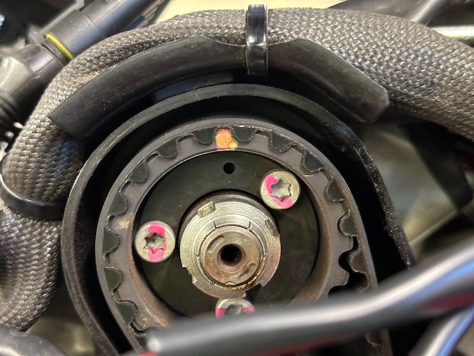
After all this hand-wringing, it’s time for me to unfloat the timing pulleys. The clamp screws are spec’d modestly at 10 N·m ± 1 N·m which, after reaching, makes me wonder just how overtorqued they had been before I performed this service. I had photos of the pulleys before I loosened them off of their hubs and it seems like the answer is a lot.
Before belt change (note that the pulley wasn’t locked at the timing datum)After
The manual does not call for retaining compound, which makes sense as the pulleys’ operating temperature would make thread locker pointless, and anyways I didn’t find any on the threads. I don’t see what else besides overtorquing could have caused such a big difference between the before and after screw positions.
Locking down the pulleys got me thinking: this procedure crystallizes an offset in phase between the driving and driven timing pulleys, meant to compensate for an equal-magnitude offset introduced by knuckling each belt with tensioners. However, that offset in each pulley set remains fixed, while the belt or its condition can change before the pulley is floated again. So if a belt has loosened up or changed without performing this “lock shafts and float pulleys” procedure, then the offset from the previous belt change makes the timing (a little) wrong.
Indeed, a test ride with this bike showed a considerable difference on the “butt dyno” report. I was accidentally lifting the front wheel on street-gentle second gear throttle rolls. Considering the EVO’s likely timing sensitivity due to its relatively low-overlap exaggerated cam lift**, it’s entirely possible that I undid some timing error introduced by a combination of the aftermarket belt and unknown “previous owner” maintenance.
At any rate, even if it’s all placebo, I still got to exercise some reverse engineering and that’s worth even more to me than the cost of labor I saved. I got to see which pieces of my machine hold up under the scrutiny of technical judgment, and which pieces are quirks that comprise… character.