HÄRDBÖRD: Hardcore Electric Longboard
So I’m going to start using my blog as a build log for projects. All the cool kids are doing it.
Introducing HÄRDBÖRD, the new reason for my keyboard layout §
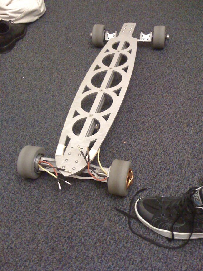
Today, I want to turn your attention to HÄRDBÖRD*, this wireless, all-aluminum electric longboard/deathtrap project I got myself involved in. My roommate Jamison and I are the principal designers (engineers? build slaves?) on a pair of these for fun and… leverage against The Man? The idea here is to get some learning done, but we do end up with ridiculously cool looking, possibly overpowered boards to ride around campus on:
I’m mostly in charge of the electronics, which are pretty simple compared to the all the other stuff. Most of it was done in about a week†. The plan is to use a Wii Nunchuk to wirelessly control the motor controllers. Why a Nunchuk? Why wireless? These transcendental questions of painful gravity are endless, but I can not answer them.
Jamison has done much of the mechanical design and machining, though I’ve been able to contribute a bit in the shop by learning the trade (i.e. the OMAX waterjet cutter in the Invention Studio at Georgia Tech). The boards are almost all waterjet-cut 6061 aluminum, with custom trucks, wheel hangers, deck—the whole shebang. We’ve run into a few snags where the wheel hangers don’t center with as much force as we’d like (in fact, not enough to be rideable); I have an elegant solution involving one spring and a cam, but it’s unmachineable and apparently patented or licensed by Original.
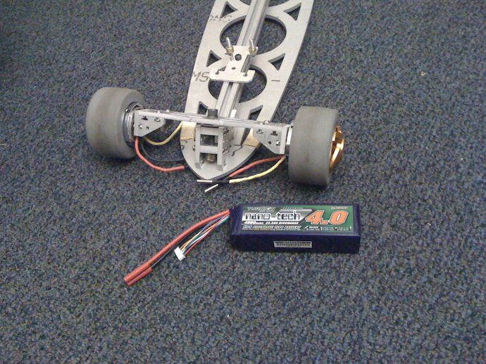
Power runs from huge 4000mAh 6S1P pack lithium-polymer batteries (22.2V nominal, 25.2V max). They’re really not that big, but I haven’t built large bots for a long while so their size still surprises me. This juice runs to a pair of Turnigy brushless motors mounted within 4-inch 30A durometer polymer-core wheels, though what goes in between the motors and the batteries is still up for debate with the bean counters—no motor control solution for the pair of the boards costs less than $300.
For more information on “getting the boards to move,” see Jamo’s posts on Härdbörd.
Meanwhile, we’re thinking of using a pair of Maxon DEC 50/5 (PDF) sensored brushless control modules. Now I’d personally prefer to build my own brushless controllers, but we really want to see this on the road. These take in a few digital signals and a 0–5V analog signal for speed. Unfortunately, everything electronic I covet and hold dear (including my low-MIPS microcontroller of choice, the Microchip dsPIC33FJ128GP802) use 3.3V, and I hate analog like that flat watered-down Sprite you get from really stingy restaurants in NYC’s Chinatown. No sir, no op-amps in my design; I’d rather drink diet.
An aside on my choice of μC §
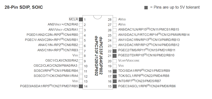
The nice thing about the dsPIC33FJ128GP802 is that it’s chock-full of every sort of peripheral, as described in its 386-page datasheet. If you don’t have a software solution, it has a hardware solution. If you don’t have a hardware solution, it has a hardware solution. If you already have a solution, IT HAS A HARDWARE SOLUTION.
In my computer architecture class, the professor was talking about the DEC VAX having a POLYD instruction to evaluate polynomials and everyone laughed at the ridiculously complex ISA co-designed by two Stuy alums. Then I realized, “dang, the dsPIC has a polynomial evaluator for CRC calculations!” Hardware bloat is not fastest in Intel’s newest SIMD floating point SSE6.8d extension, but in these little 8- and 16-bit nuggets by means of the memory-mapped peripheral.
I mean seriously, in addition to the usual timers, ADCs, I²C, SPI, U(S)ARTs, CAN, and other junk, it’s got freaking DMA and multi-priority interrupt system for all of those. Then they decide that wasn’t enough and crammed an extra ALU and barrel shifter in there with 40-bit accumulators and called it a DSP engine. But wait, there’s more! There’s more space on the die! Let’s shove a comparator and a real-time clock in there! Now they had more hardware than they had pins, so what do they do? STICK MUXES AND TRISTATE DRIVERS EVERYWHERE. Yeah, that’s right, almost every peripheral on this thing can be mapped to any pin. This thing even solves your PCB layout issues because you can reconfigure your pinout in software.
Oh yeah, this thing also doesn’t need a crystal to run at its full 40MIPS, has a free official GCC compiler, and comes in 28-pin breadboadable through hole (as free samples!). Life doesn’t get more perfect.
The receiver §
Aside aside, I wanted to output 0–5V analog from my dsPIC33F. Well, first thing I see is that it’s got this DAC peripheral. Everything is fine and dandy unti—AUGH IT OUTPUTS A DIFFERENTIAL SIGNAL. In other words, not only is it not 0–5V, it’s not even 0–3.3V. It’s some janky 0.8–2.8V (-ish. Don’t quote me.) swing for audio use. Darn, now I have to ghetto-hack a DAC from the PWM hardware.
Fortunately, this is extremely straightforward. The Output Compare module, as the “PWM” module is called in the dsPIC33F/PIC24H lines, is one of the most pleasant hardware peripherals I’ve ever used, on any computer, ever. Put it like this: it’s easier than the software way. You set up a timer with some prescaler values against system clock, as well as a period match register for when it should reset the timer counter to 0. That’s right: not only can you set the frequency of the timer tick, but also the period by which it resets. Awsm.
static inline void configTimer2(void) {
	T2CON = T2_OFF | T2_IDLE_CON | T2_GATE_OFF | T2_32BIT_MODE_OFF | T2_SOURCE_INT | T2_PS_1_1;
	PR2 = usToU16Ticks(PWM_PERIOD, getTimerPrescale(T2CONbits)) - 1;
	TMR2 = 0; //clear timer2 value
	_T2IF = 0;
	_T2IP = 1;
	_T2IE = 1; //enable the Timer2 interrupt
}
Anyways, next you just set up the output compare module to use that timer.
static inline void configOutputCompare1(void) {
	T2CONbits.TON = 0; //disable Timer when configuring Output compare
	CONFIG_RB14_AS_DIG_OUTPUT();
	CONFIG_OC1_TO_RP(14); //map OC1 to RP14/RB14
	//assumes TIMER2 initialized before OC1 so PRE bits are set
	OC1RS = 0; //initially off
	//turn on the compare toggle mode using Timer2
	OC1CON = OC_TIMER2_SRC | //Timer2 source
			OC_PWM_FAULT_PIN_DISABLE; //PWM, no fault detection
}
The way this work is basically described by this timing diagram:
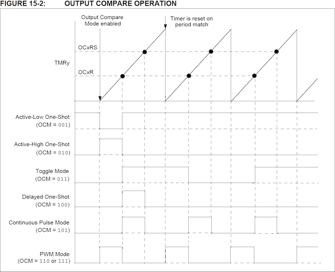
When the timer counter is less than register OC1RS, the OC1 pin (reconfigured by software as described above, to RP14) is output high. Otherwise, it’s output low. The period of rollover is defined by the timer’s period register PR2. In other words, the duty cycle (and thus average voltage) is exactly‡ OC1RS/PR2.
Aside: you know why this would be useless on your ATMEGATRON9000KFLASH4BYTERAM AVRDUINO CAPPUCCINO2001 device? It’s 8-bit. All of these registers would be 8-bit, and you’d either have crappy 8-bit timers that can’t do straightforward PWM like this or some janky concatenated 2×8-bit monster with terrible latency and 40 pages in errata. End aside.
OK, so now we know how the PWM works. But how do we get 5V output? Surely we’ll need an op amp to up our range to fiv—CATSLAP. We don’t like your kind here.
Yeah, so there’s a dsPIC peripheral solution here. The digital pins on the dsPIC have an open-drain operation mode§. A pin in open-drain output mode is hard pull to low (drain) when its port register bit is 0, and tristated (high-impedance, Z, floating) when its bit is 1. This means you can hook up 5V pull-up resistor to it, and get 5V output from a 3.3V device.
Now all I need to do is feed that 5V signal to a RC filter tuned to attenuate the PWM frequency, and I’ll have a clean 5V DAC output. I feel like freaking 诸葛亮 right here.
The test §
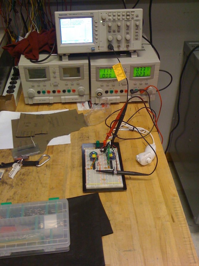
I’m working on all of this in the Invention Studio because I want an oscilloscope for this. Now the Invention Studio is an Mechanical Engineering shop, so the o-scope is a bit dinky, but hey, it’s digital, there are working probes around, and it works… for the most part.

Anyways, I don’t have real o-scope captures, so bear with my cellphone camera photos of the various test cases. So here’s the circuit under test:
Now let’s get some data:
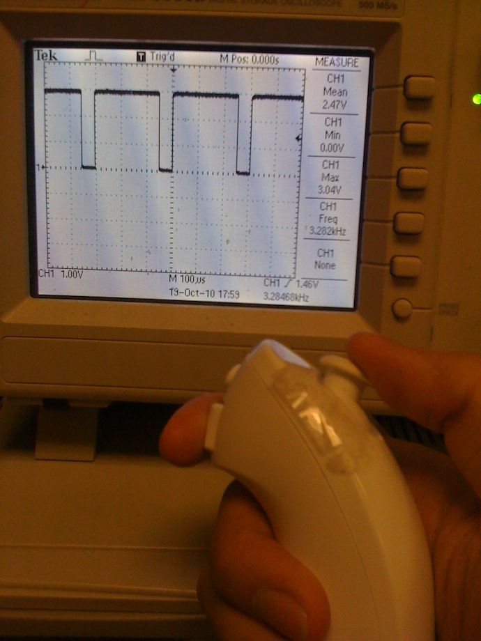
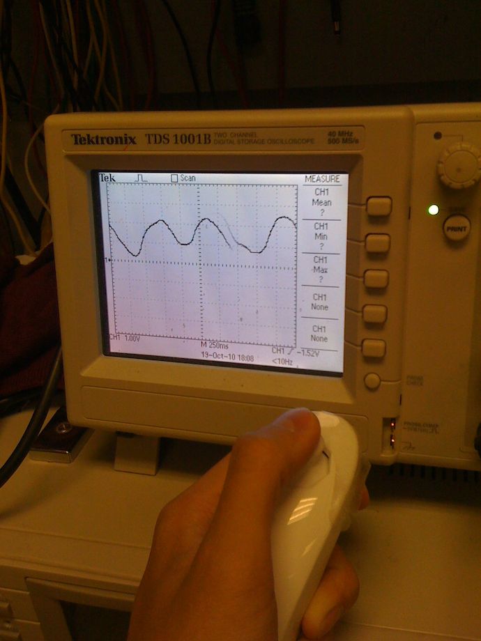
Being able to adjust the duty cycle of the waveform with a joystick is some hot stuff, especially if you fiddle with the trigger settings a bit. Now let’s hook up a 100KOhm×0.1μF RC filter on that. This has a cutoff frequency of about 16Hz, at which point half the signal is attenuated. Higher frequency signals are attenuated at 20dB per decade, so the 3.28kHz PWM frequency is attenuated by at least 40dB. Good enough for me to play Etch-A-Sketch on the scope with my Nunchuk:
And just for the hell of it, I measured the ripple of the analog:
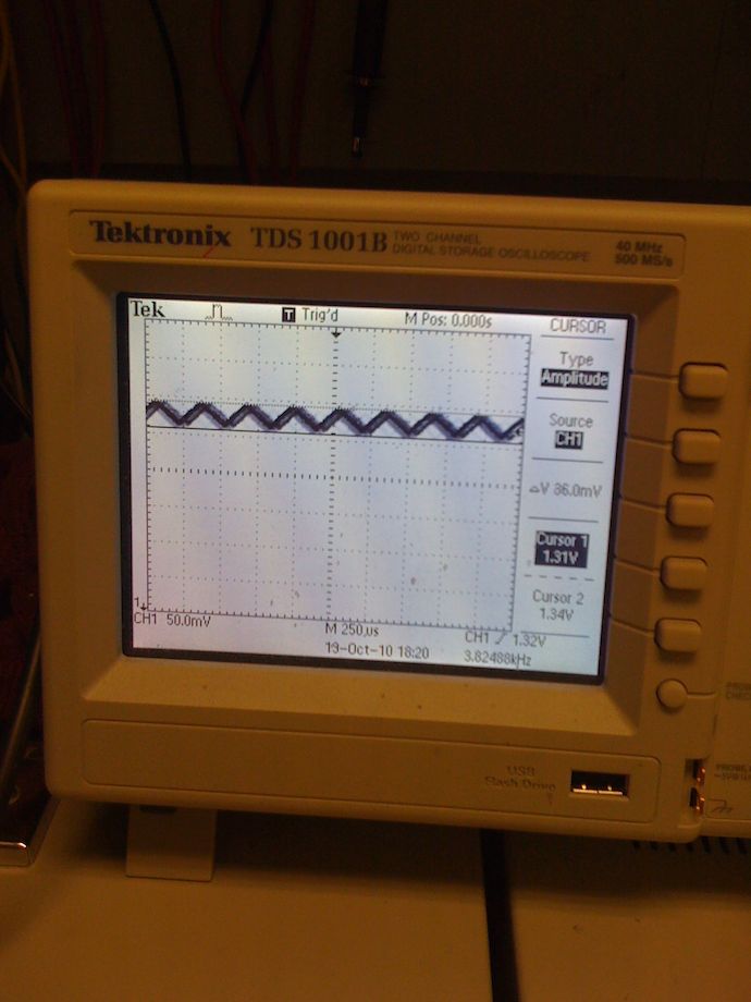
About 30mV. Not bad. Taking this measurement was a real pain: I had to keep my joystick finger steady while zooming/panning on a tiny sliver of the vertical scale, throw in measurements, and praying that a little twitch won’t throw the waveform off the triggering level.
So, that concludes this really boring part of “reducing part count of everything to just a dsPIC.” Next time, I’ll show how I did this with the transmitter side.